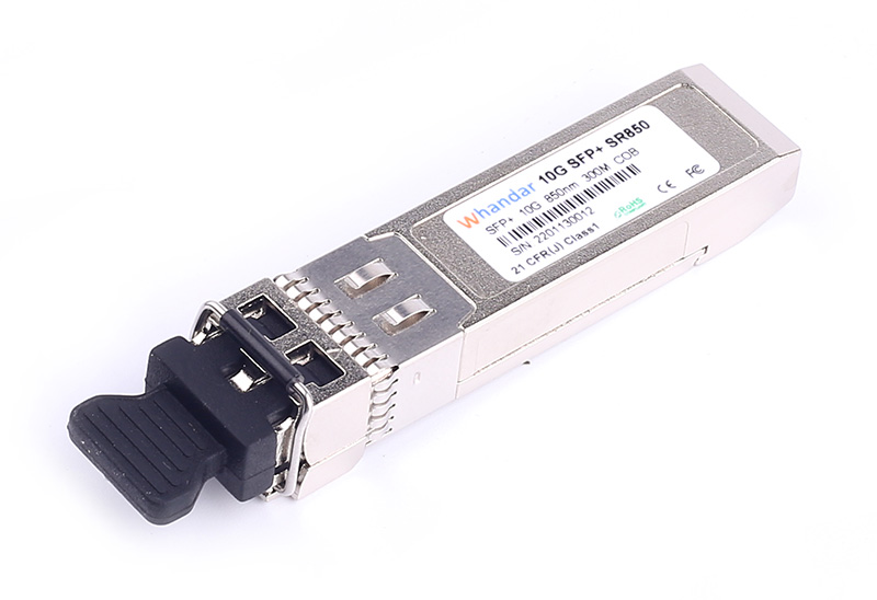
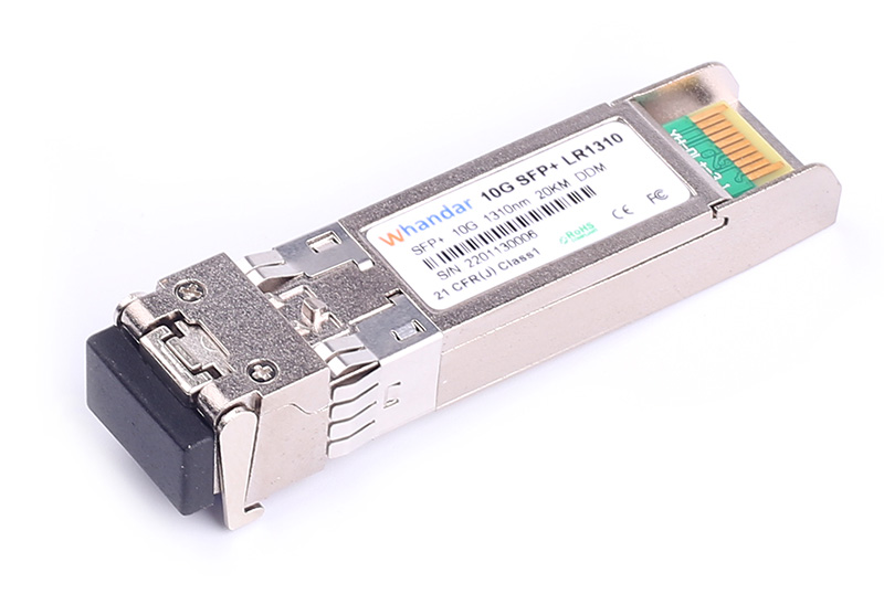
SFP-10G-SR 10G SFP + SR 850nm 300m LC MMF DDM модуль приемопередатчика
-
Дуплексный SFP+ многомодовый трансивер
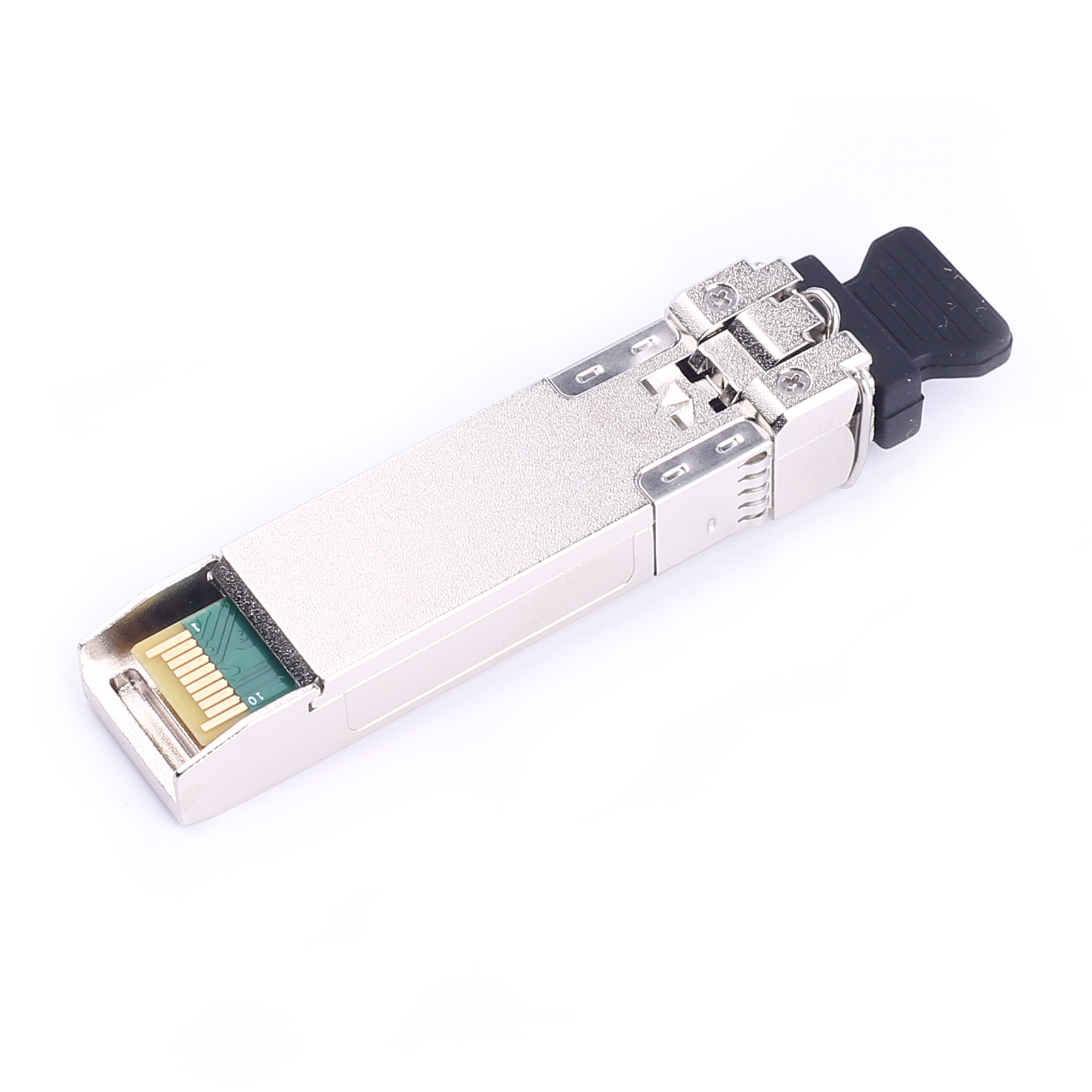
С возможностью горячей замены
Разъем LC
Оптический интерфейс, соответствующий стандарту IEEE 802.3ae
Электрический интерфейс, соответствующий стандарту SFF-8431 -
Двухволоконный SFP+ модуль предназначен для передачи данных на длине волны 850 нм по двум волокнам. Оснащен оптическим разъемом LC. Обеспечивает передачу данных со скоростью 10 Гбит/с на расстояние 300 м (0.3 км).
Наличие функции цифрового оптического контроля DDM позволяет контролировать важные параметры: выходную/входную мощность, температуру, ток и прочие. Использование цифровой диагностики дает возможность оценить уровень износа оптической системы и общее состояние трассы.
информация о продукте
| Номер изделия | HD-SFP+/10G-SR | Название поставщика | Handar/OEM |
| Форм-фактор | SFP + | Максимальная скорость передачи данных | 10.7Gbps |
| Длина волны | 850nm | Макс. Расстояние | 300 м на OM3? |
| соединитель | Дуплексный ЖК | Тип передатчика | VCSEL 850 нм |
| Тип кабеля | ММФ | Тип приемника | PIN-код |
| TX Power | -6.5 ~ -0.5dBm | Чувствительность приемника | <-10.5 дБм |
| протоколы | 10G Ethernet, соответствие требованиям MSA | Рабочая Температура | От 0 до 70 ° C |
Сертификация качества
Нужна помощь? Свяжитесь с нашими экспертами по продукции или отделом продаж уже сегодня!
Похожие товары
Последние новости и блог
-
2025-08-05
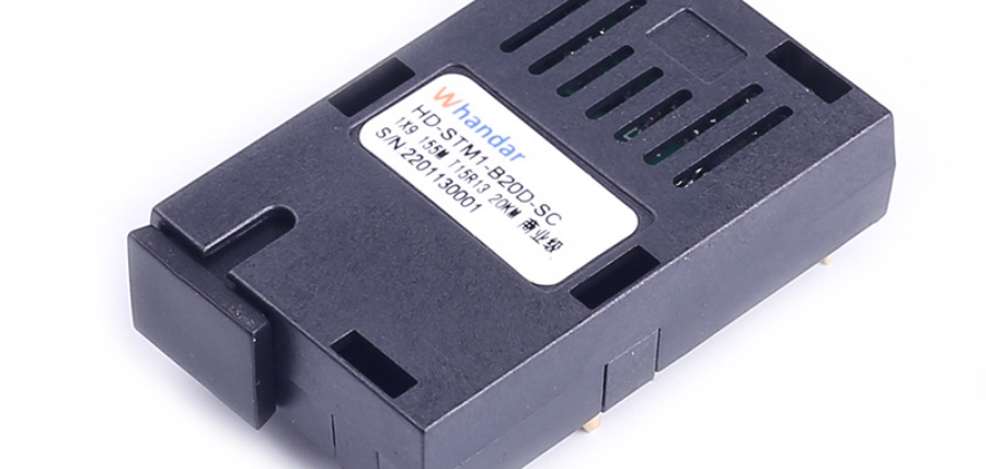
Применение и преимущества оптических трансиверов 1×9 в системах промышленной печати
По мере развития промышленной автоматизации и интеллектуального производства коммуникационные системы промышленного печатного оборудов…

-
2025-08-05
Применение оптических модулей в топологии ячеистой сети
Рассмотрите использование топологии ячеистой сети для удовлетворения ваших потребностей в коммуникации и передаче данных. В данной статье…

-
2025-08-05
Расширение перспектив коммуникаций благодаря технологии OTN
В современном быстро развивающемся цифровом пространстве потребность в надежной и эффективной передаче данных стала как никогда актуальн…