Увеличить
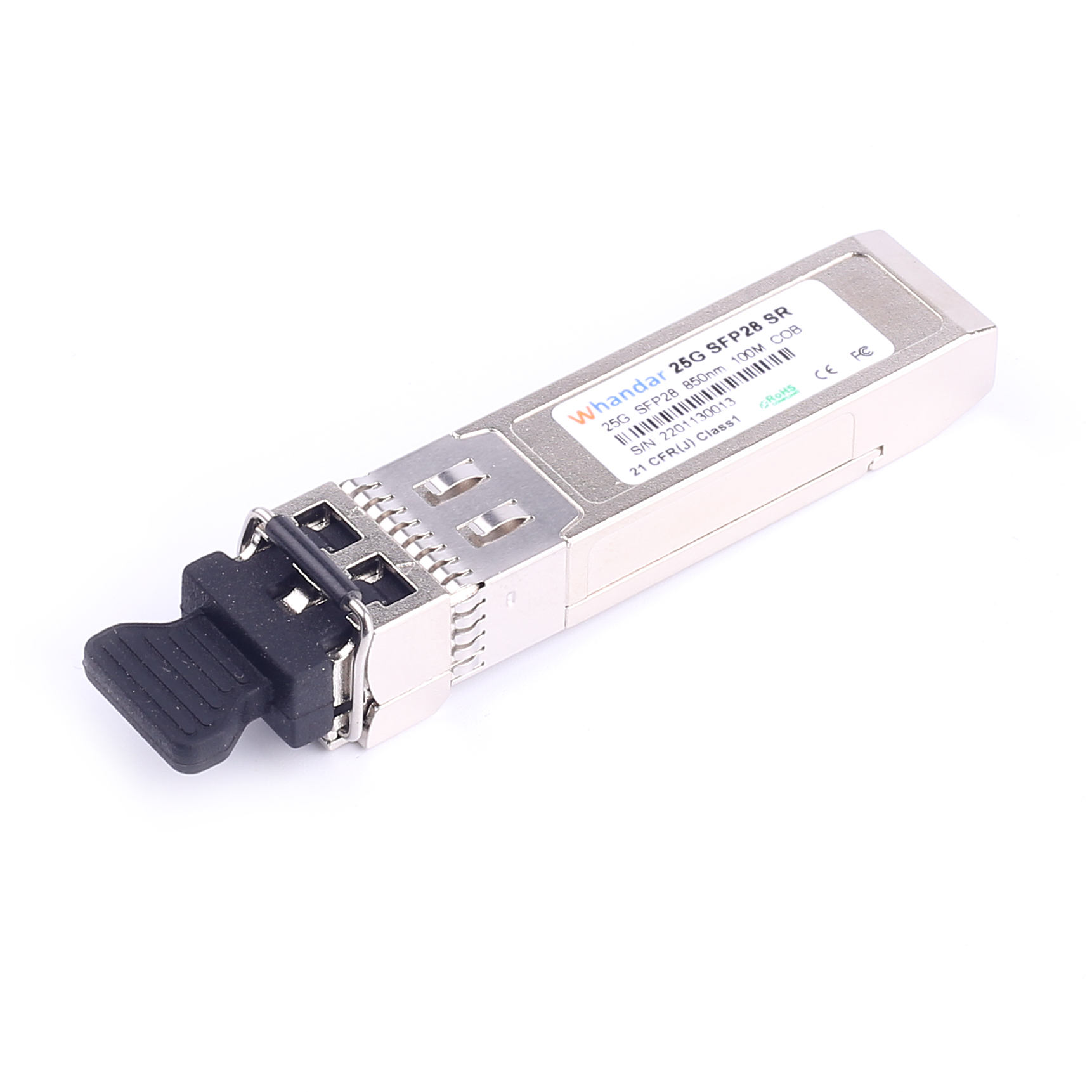
SFP28-25G-SR Модуль приемопередатчика 25G SFP28 SR 850nm 100m LC MMF DDM
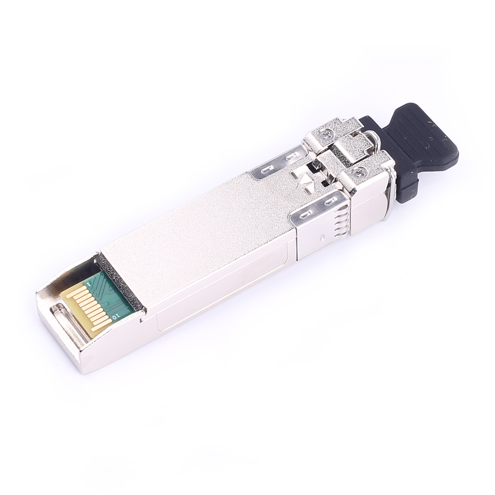
Дуплексный трансивер SFP28
Разъем LC
Скорость передачи данных до 25,78125 Гбит/с
Лазер VCSEL 850 нм и фотодетектор PIN
Максимальная длина линии связи 70 м на многомодовом оптоволокне OM3 и 100 м на многомодовом оптоволокне OM4
Модуль приемопередатчика 25G SFP28 SR (850 нм MMF, 100 м LC DDM)
Приемопередатчики 25G SFP SR предназначены для передачи данных со скоростью 24.33 Гбит/с и 25.78 Гбит/с по MMF и поддерживают длину канала до 100 м на OM4 и 70 м на OM3. Они совместимы с IEEE802.3by, SFF-8402 и SFF-8432. Интерфейс цифрового диагностического мониторинга, совместимый с SFF-8472, доступен через интерфейс I2C.
информация о продукте
| Номер изделия | HD-SFP28/25G-SR | Название поставщика | Handar/OEM |
| Форм-фактор | SFP28 | Максимальная скорость передачи данных | 25 Gbps |
| Длина волны | 850nm | Макс. Расстояние | 70 м над OM3 / 100 м над OM4 |
| соединитель | Дуплексный ЖК | Тип передатчика | 850nm |
| Тип кабеля | ММФ | Тип приемника | PIN-код |
| TX Power | -6.0 ~ + 2.4dBm | Чувствительность приемника | <-10.3 дБм |
| протоколы | MSA-совместимый | Рабочая Температура | От 0 до 70 ° C |
Сертификация качества
Мы контролируем качество нашей продукции, включая строгую квалификацию производителей, процесс контроля качества и технологию производства, а также соответствие стандартам сертификации и безопасности. В настоящее время наша продукция соответствует отраслевым стандартам и основным сертификатам качества, таким как ISO 9001, CE, RoHS, FCC и т. д.
Нужна помощь? Свяжитесь с нашими экспертами по продукции или отделом продаж уже сегодня!
Последние новости и блог
-
2025-08-05
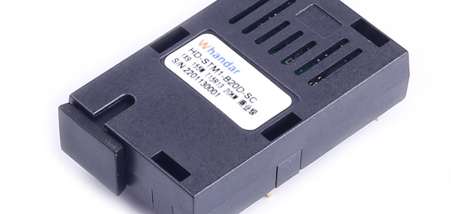
Применение и преимущества оптических трансиверов 1×9 в системах промышленной печати
По мере развития промышленной автоматизации и интеллектуального производства коммуникационные системы промышленного печатного оборудов…
-
2025-08-05
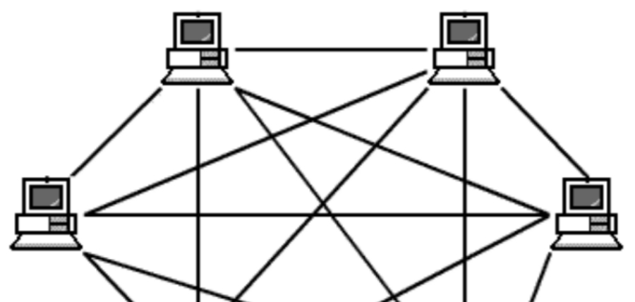
Применение оптических модулей в топологии ячеистой сети
Рассмотрите использование топологии ячеистой сети для удовлетворения ваших потребностей в коммуникации и передаче данных. В данной статье…
-
2025-08-05
Расширение перспектив коммуникаций благодаря технологии OTN
В современном быстро развивающемся цифровом пространстве потребность в надежной и эффективной передаче данных стала как никогда актуальн…