ХАРАКТЕРИСТИКИ ИЗДЕЛИЯ
Двунаправленная передача данных со скоростью до 1,25 Гбит/с
Возможность горячей замены SFP-модуля
Низкое энергопотребление (типичное значение 1,05 Вт)
Полностью металлический корпус для снижения электромагнитных помех
Соответствие RoHS 6 и отсутствие свинца
Однополярное питание +3,3 В
Работа по стандарту 10/100/1000 BASE-T в хост-системах с интерфейсом SGMII
Рабочая температура окружающей среды: от 0°C до +70°C
Распиновка разъема SFP-хост
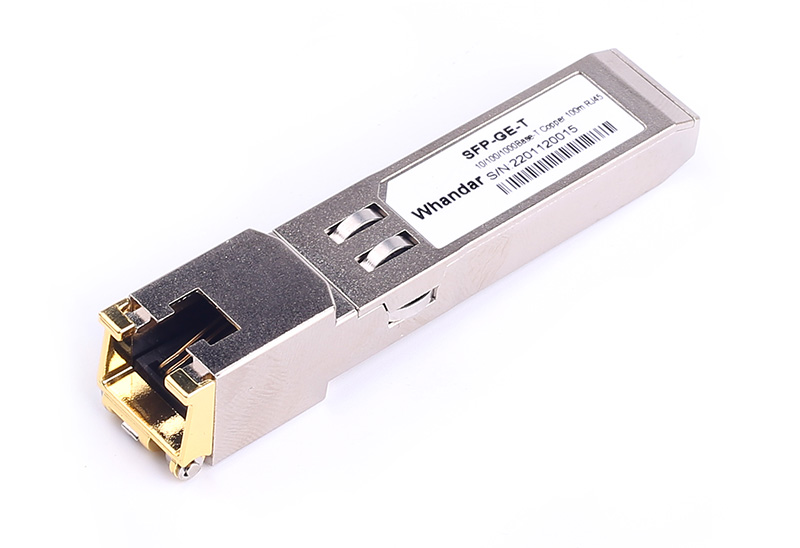
информация о продукте
| Номер изделия | HD-GLC-T | Название поставщика | Handar/OEM |
| Форм-фактор | SFP | Скорость передачи данных | 10 / 100 / 1000Mbps |
| Тип кабеля | Кошка 5 | Кабельное расстояние | 100m |
| Интерфейс | RJ-45 | Поддержка DDM | Нет |
| протоколы | Совместимость с MSA, IEEE STD 802.3 и 802.3ab | Рабочая Температура | От 0 до 70 ° C |
Информация для заказа
|
Номер детали изделия |
Product DescriptionОписание продукта |
|
HD-GLC-TSD |
SFP-T-10-100-1000BASE AUTO Copper SFP , SerDes
|
|
HD-GLC-TSG |
SFP-T-10-100-1000BASE AUTO Copper SFP , SGMII
|
Сертификация качества
Нужна помощь? Свяжитесь с нашими экспертами по продукции или отделом продаж уже сегодня!
Похожие товары
Последние новости и блог
-
2025-08-05
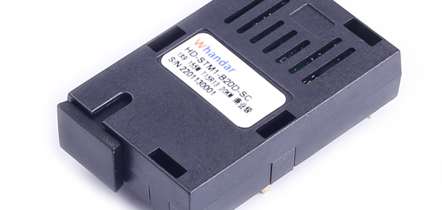
Применение и преимущества оптических трансиверов 1×9 в системах промышленной печати
По мере развития промышленной автоматизации и интеллектуального производства коммуникационные системы промышленного печатного оборудов…
-
2025-08-05
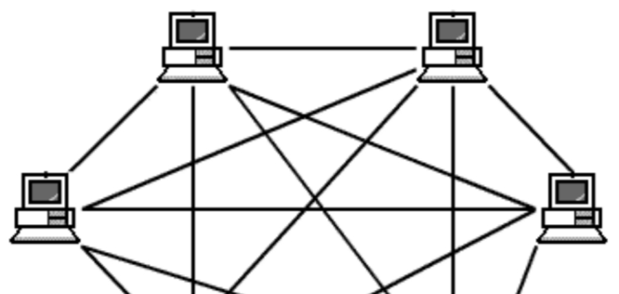
Применение оптических модулей в топологии ячеистой сети
Рассмотрите использование топологии ячеистой сети для удовлетворения ваших потребностей в коммуникации и передаче данных. В данной статье…

-
2025-08-05
Расширение перспектив коммуникаций благодаря технологии OTN
В современном быстро развивающемся цифровом пространстве потребность в надежной и эффективной передаче данных стала как никогда актуальн…