Features:
Customized 2Mb/s , 84Mb/s low rate optical modules for your own applications
Can offer up to 3G rate optical module fitting to your applications
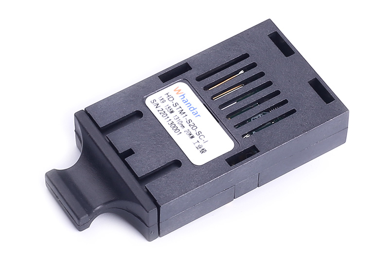
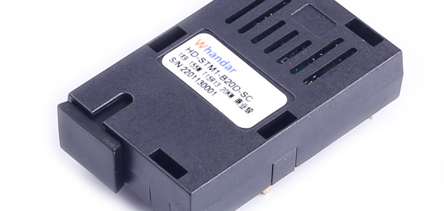
SC/FC/ST optional optical interface transceiver module
Single +3.3V Power Supply
1×9 package
High quality FP/DFB/CWDM Laser
PECL compatible data input/output interface
PECL receiver signal-detected indication
Industrial level : -40℃ to +85℃ operating temperature range
Applications:
Industrial 2Mb/s, 84Mb/s , 155Mb/s ,1.25Gb/s,2.5Gb/s Fiber transmission systems, example the Industrial Fiber Ethernet Switches ,PDH/SDH Fiber optical converters , Analog video to fiber converters ...etc.
Absolute Maximum Ratings
|
Parameter |
Symbol |
Unit |
Min |
Max |
|
Ambient Operating Temperature Range |
TOP |
℃ |
-40 |
+85 |
|
Storage Temperature Range |
Ts |
℃ |
-40 |
+85 |
|
Relative Humidity |
RH |
% |
0 |
85 |
|
Power supply Voltage |
Vcc |
V |
3.14 |
3.47 |
|
Lead Solder Temperature |
- |
℃ |
- |
260 |
|
Lead Solder Duration |
- |
S |
- |
10 |
Recommended Operating Conditions
|
Parameter |
Symbol |
Unit |
Min |
Typ |
Max |
|
Operating Temperature Range |
Top |
℃ |
-40 |
- |
85 |
|
Power Supply Voltage |
Vcc |
V |
3.14 |
3.3 |
3.47 |
|
Operating Data Rate |
- |
Mpbs |
- |
1.25G |
- |
ifications (Top= -25℃, BOL, unless otherwise noted)
|
Parameter |
Symbol |
Unit |
Min |
Typ |
Max |
Test condition |
|||
|
Electrical Characteristics |
|||||||||
|
|
Tx section |
Icc |
m |
- |
- |
120 |
|
||
|
Rx section |
- |
- |
120 |
|
|||||
|
Vin |
mV |
400 |
800 |
1800 |
|
||||
|
- |
Mbps |
- |
1250 |
- |
|
||||
|
Power |
20km |
Po |
dBm |
-9 |
- |
-3 |
1.3umFP |
||
|
λc |
nm |
1280 |
1310 |
1340 |
1.3umFP |
||||
|
Extinction Ratio |
ER |
dB |
9 |
- |
- |
|
|||
|
FP-LD (RMS) |
∆λ |
nm |
- |
- |
4 |
|
|||
|
Optical receive Characteristics |
|
||||||||
|
Optical receive Characteristics |
|||||||||
|
- |
Mbps |
- |
1250 |
- |
|
||||
|
Sensitivity |
S |
dBm |
- |
- |
-23 |
|
|||
|
POL |
dBm |
-3 |
- |
- |
|
||||
|
- |
dB |
-35 |
- |
- |
|
||||
|
- |
- |
- |
-24 |
|
|||||
|
- |
dB |
0.5 |
|
6 |
|
Pin Connections
|
Pin |
Name |
Level |
Description |
|
1 |
VEER |
|
Negative power of receiver section, normally grounded |
|
2 |
RD+ |
PECL |
Receiver Date out, Terminate this pin with standard PECL techniques |
|
3 |
RD- |
PECL |
Reverse Receiver date out, Terminate this pin with standard PECL techniques |
|
4 |
SD |
PECL |
Optical alarm of receiver section, High level when normal, low level when no light |
|
5 |
VccR |
|
Positive power of receiver section, normally +5V |
|
6 |
VccT |
|
Positive power of transmitter section, normally +5V |
|
7 |
TD- |
PECL |
Reverse data input of transmitter section |
|
8 |
TD+ |
PECL |
Date input of transmitter section |
|
9 |
VEET |
|
Negative power of transmitter section, normally grounded |
Typical Application Circuit

Package Outline: (unit mm)

Regulatory Compliance
|
Feature |
Test Method |
Performance |
|
Electrostatic Discharge (ESD) to the Electrical Pins |
MIL-STD-883E Method 3015.7 |
Class 1 (>1.5kV) – Human Body Model |
|
Electrostatic Discharge (ESD) Immunity |
IEC61000-4-2 |
Class 2 (>4.0kV) |
|
Electromagnetic Interence (EMI) |
CISPR22 Class B EN55022 Class B |
Compliant with standards |
|
Immunity |
IEC61000-4-3 Class 2 EN55024 |
Typically show no measurable effect from a 3V/m field swept from 80 to 1000MHz applied to the transceiver without a chassis enclosure. |
|
Eye Safety |
FDA 21 CFR 1040.10 and 1040.11 |
Compliant with Class 1 laser product UL No.E239070 |
|
UL |
||
|
TUV EN 60825-1 |
Нужна помощь? Свяжитесь с нашими экспертами по продукции или отделом продаж уже сегодня!
Похожие товары
Последние новости и блог
-
2025-08-05
Применение и преимущества оптических трансиверов 1×9 в системах промышленной печати
По мере развития промышленной автоматизации и интеллектуального производства коммуникационные системы промышленного печатного оборудов…
-
2025-08-05
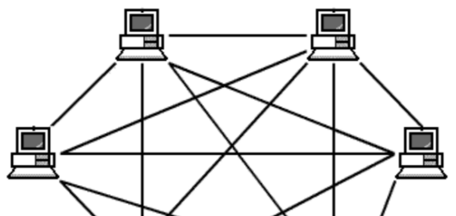
Применение оптических модулей в топологии ячеистой сети
Рассмотрите использование топологии ячеистой сети для удовлетворения ваших потребностей в коммуникации и передаче данных. В данной статье…

-
2025-08-05
Расширение перспектив коммуникаций благодаря технологии OTN
В современном быстро развивающемся цифровом пространстве потребность в надежной и эффективной передаче данных стала как никогда актуальн…